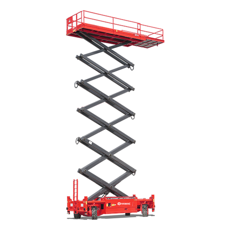
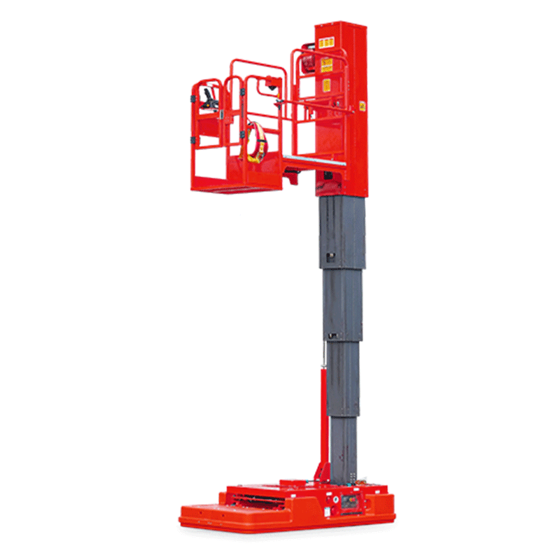
Vertical Lifts
Aerial Work Platforms
Max Working Height:5.8–10.3 m
Platform Capacity:160–227 kg
Consult now






One of the most misunderstood aspects of telehandler operation is the load chart. Many buyers see a telehandler's advertised "maximum lifting capacity" — for example, 3,500 kg or 5,000 kg — and assume this weight can be lifted anywhere within the machine's working range. In reality, a telehandler's true lifting capacity changes constantly depending on boom angle, lift height and forward reach, and the load chart is the only reliable reference for how much weight can be safely lifted at any given position.
As a manufacturer of the HT series telehandlers, HAMAC provides load charts with every unit and regularly helps customers and operators understand how to interpret them correctly. This guide explains the load chart step by step so buyers and operators can plan lifts safely and select the right machine for their tasks.
A load chart, sometimes called a load capacity chart, is a grid-based diagram that shows the maximum safe load a telehandler can lift at every combination of lift height and forward reach. It is specific to a single machine model, and often specific to a particular attachment (forks, bucket, jib), because rated capacity changes depending on what is mounted on the carriage.
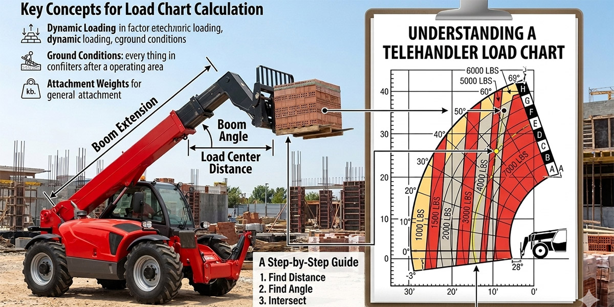
| Chart Element | Location on Chart | What It Represents |
|---|---|---|
| Lift Height | Vertical axis (left side) | The vertical distance from the ground to the load placement point |
| Forward Reach | Horizontal axis (bottom) | The horizontal distance from the front of the machine to the load |
| Load Capacity | Numbers within the grid / boom angle lines | The maximum safe weight at the intersection of a specific height and reach |
A telehandler's stability depends on the relationship between the load, the boom's extension, and the machine's counterweight. As the boom extends further forward or is raised to a steeper angle, the load's weight creates a greater tipping moment around the front axle. This is why the rated capacity at maximum forward reach is always significantly lower than the rated capacity close to the machine — often only a fraction of the maximum advertised lifting capacity. A telehandler advertised with a "4,000 kg" maximum capacity may only be able to lift a few hundred kilograms at its maximum reach.
| Step | Action |
|---|---|
| 1 | Confirm the chart matches your exact machine model and the attachment currently mounted (forks, bucket or jib). |
| 2 | Determine the true load weight, including the pallet, rigging or attachment weight if applicable — not just the material itself. |
| 3 | Confirm the load center distance. Most charts are based on a standard load center (commonly around 500–600 mm); loads with a longer center reduce the safe capacity. |
| 4 | Identify the required lift height on the vertical axis. |
| 5 | Identify the required forward reach on the horizontal axis. |
| 6 | Find where the height and reach intersect on the chart, and read the maximum permitted load capacity at that point. |
| 7 | Compare your actual load weight to the charted capacity. If your load exceeds the charted value, the lift is not safe at that position. |
Many telehandler load charts divide the working envelope into lettered zones, typically ranging from A to H. Zones closest to the machine (such as Zone A) generally permit the heaviest loads, while zones farther away or higher up (such as Zone H) permit progressively lighter loads. This zone system makes it easier for operators to quickly reference approximate safe capacity without recalculating exact coordinates every time, though the precise chart values should always be used for actual lift planning.
| Mistake | Risk | Correct Practice |
|---|---|---|
| Using the machine's maximum advertised capacity for all lifts | Overloading at height or reach, risk of tip-over | Always check the charted capacity at the specific height and reach being used |
| Ignoring load center differences | Reduced actual capacity not accounted for | Recalculate capacity using the load center reduction factor if the load center exceeds the chart's standard |
| Referencing a chart for a different attachment | Incorrect capacity assumptions | Only use the chart specific to the attachment currently mounted |
| Disregarding outrigger position notes | Using a higher capacity than actually available | Confirm whether the chart applies to outriggers up or down before lifting |
When comparing telehandler models, buyers should not rely solely on the maximum advertised lift capacity or maximum lift height listed in a spec sheet. Instead, buyers should request the load chart for the specific model and attachment configuration and confirm that the required load weight can be safely lifted at the height and reach needed for the actual jobsite tasks — not just at the machine's most favorable lifting position.
Send us your required lift height, forward reach, load weight and attachment type. Our team will provide the applicable load chart and confirm whether a HAMAC telehandler model can safely perform the lift.
Q1: Why is a telehandler's real lifting capacity lower than its advertised maximum?
The advertised maximum capacity is only achievable close to the machine at a low lift height. As the boom extends forward or upward, the tipping moment increases and the safe load capacity decreases significantly, as shown on the load chart.
Q2: What is load center, and why does it matter on a load chart?
Load center is the horizontal distance from the face of the forks to the center of gravity of the load. Most load charts are based on a standard load center; loads with a longer center of gravity reduce the machine's safe lifting capacity at any given height and reach.
Q3: Does the load chart change if I use a bucket instead of forks?
Yes. Different attachments shift the load's weight distribution and center of gravity, so each attachment typically has its own load chart or capacity adjustment factor.
Q4: What happens if I lift a load heavier than the chart allows at a given position?
Exceeding the charted capacity at a specific height and reach increases the risk of the telehandler tipping forward, which is a serious safety hazard. Operators should always stay within the values shown on the applicable load chart.
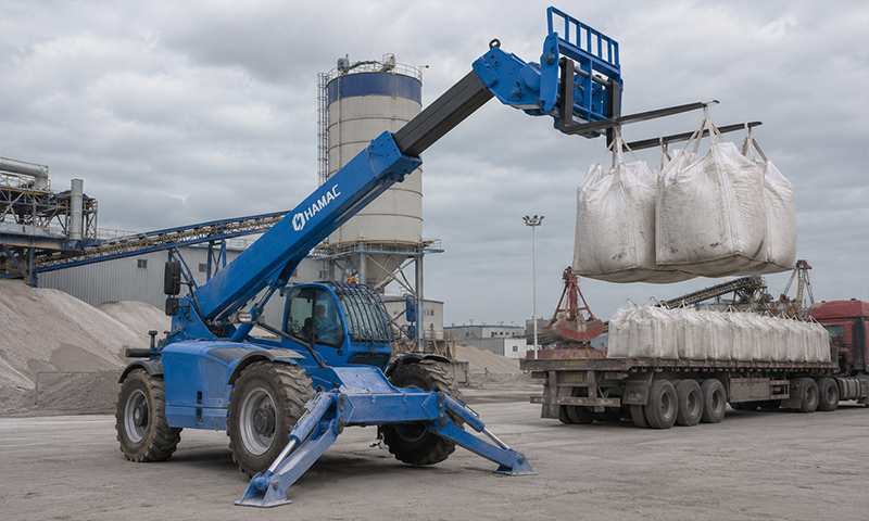
At inland port terminals, a high‑capacity telehandler is used to transfer bulk materials between tr
Free Consultation >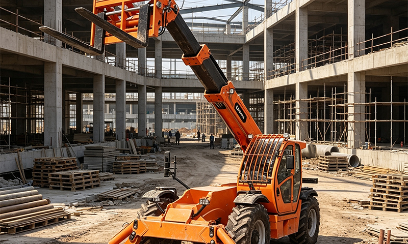
This case study describes how an HT5014 telehandler supports outdoor storage rack replenishment besid
Free Consultation >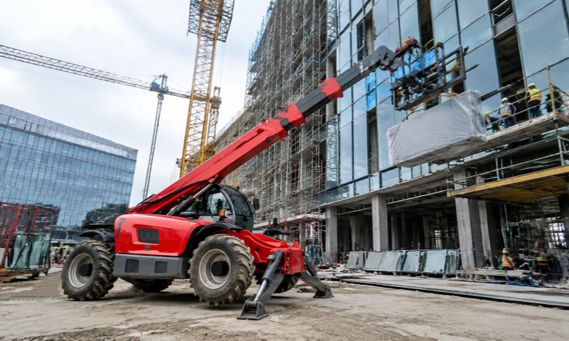
On a commercial building project, an HT4010 telehandler is used to assist facade and curtain wall ins
Free Consultation >Please fill out the form, and we can satisfy any of your needs including equipment selection, scheme design, technical support, or after-sales service. We will contact you as soon as possible.